Title : Field Winding Symbol
Link : Field Winding Symbol
Field Winding Symbol
As each coil is energized in turn the rotor aligns itself with the magnetic field produced by the energized field winding. AC Injection Method of Rotor Earth Fault Protection in Alternator.

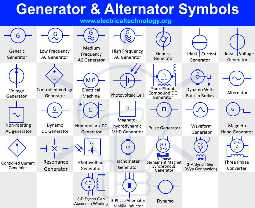
Generator Symbols Alternator Symbols Electrical Technology
The shunt field resistance is 110 Ω and there are 2500 turns per pole.

Field winding symbol. If this push button is pressed the center tap is shift and the voltage will appear across the relay even in the event of central arc fault occurs on the field winding. The beginning of the turn or coil is identified by the symbol S meaning Start and the end of the turn or coil is represented by the symbol. A Shaded Pole Electric Motor is a single phase induction motor provided with an auxiliary short-circuited winding or windings displaced in magnetic position from the main winding.
The symbol for an air-core transformer is shown in figure 7-A. A field winding is the insulated current-carrying coils on a field magnet that produce the magnetic field needed to excite a generator or motor. The rotor magnetic field.
A the range of external field-circuit resistance necessary to vary the voltage from 220 V on full load to 170 V on no load when the speed is 500 revmin. And series field coil is exposed to the entire supply current before being split up into armature and shunt field. Using a field winding means you can create a.
Ad Healthier Livestock and Pastures - Lightweight Towed Manure Collectors. Here one voltage sensitive relay is connected at any point of the field. The AC motor commonly consists of two basic parts an outside stator having coils supplied with alternating current to produce a rotating magnetic field and an inside rotor attached to the output shaft producing a second rotating magnetic field.
In case of short shunt compound wound DC motor the shunt field winding is connected in parallel across the armature winding only. In a lap winding there are as many current paths between the brush or line connections as there are poles in the field winding. Reversal of the motor is accomplished by interchanging the field winding connections.
The manual says that 60 watts maximum should go to the field winding. Ad Healthier Livestock and Pastures - Lightweight Towed Manure Collectors. ˈwaɪndɪŋ.
A DC shunt motor also known as a shunt wound DC motor is a type of self-excited DC motor where field winding is shaken or connected parallel to the armature winding of the motor. Because they are connected in parallel the armature and field winding. An AC motor is an electric motor driven by an alternating current.
Field winding in Electrical Engineering. A field winding or field coil is used to create a magnetic field that is typically used to operate an electric motor. The rotor contains the field winding wound over an iron core which is part of the shaft.
In a wave winding there are. Surrounding the field coil are two claw-type finger poles. Each end of the rotor field winding.
As the lines of flux expand outward relative motion is present and a counter emf is induced in the winding. Shaded Pole Electric Motor. The following letters and symbols shall be used for motors and generators and their auxiliary devices when they are included within or mounted on the machine Resistance shunt field.
When an alternating current flows through a primary winding a magnetic field is established around the winding. Parts B and C show iron-core transformers. The insulated current-carrying coils on a field magnet that produce the magnetic field intensity required to set up the.
According to theory amps watts over volts so the amps to the field winding should be 60watts the desired wattage to the field winding. The figure of the winding is shown below.

Types Of Dc Generators Diagrams Included Electrical4u

Self Excited Dc Generators Electrical4u

Diagram Wire Diagram Motor Symbol Full Version Hd Quality Motor Symbol Dogday Museogilardi It
Types Of Dc Machine Electrical Article

Series Wound Dc Motor Or Dc Series Motor Electrical4u

Drafting For Electronics Motors And Control Circuits Part 1

Hydraulic Electric Analogies Part 4 Comparing Power Sources Hydraulics Pneumatics
Inductor Choke Coil Transfomer Circuit Symbols Electronics Notes

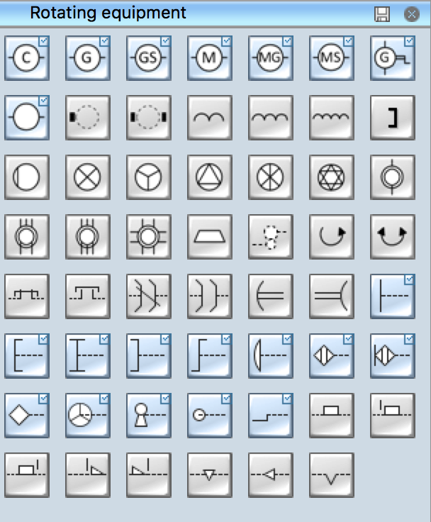
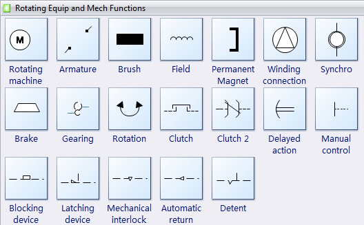
Electrical Symbols Rotating Equipment

Construction Of Dc Generator Each Part Explanation

Construction Of Dc Motor Parts Images Electrical4u
Electrical Symbol Electrical Engineering Interview Questions Facebook

Electrical Motor Symbols Electric Motors Are Electromechanical Devices Whose Function Is To Transform Electrica In 2021 Electrical Motor Electricity Electrical Motors

Symbolic Representation Of D C Generator Electrical Engineering Interview Questions

Drafting For Electronics Motors And Control Circuits Part 1

Design Elements Transformers And Windings Design Elements Rotating Equipment Electrical Engineering Symbol Of Winding

Dc Shunt Motor Speed Control Characteristics Electrical4u
Thus this article Field Winding Symbol
You are now reading the article Field Winding Symbol with the link address https://wiringdiagramcorner.blogspot.com/2022/02/field-winding-symbol.html


